FreeCAD Tutorial: Design a Parametric Box with Custom Dimensions
This FreeCAD tutorial will guide you through designing a parametric box from scratch. Learn how to use formulas and constraints to create a 3D model with easily adjustable custom dimensions.

Man, sometimes I look at a custom order request and just sigh, you know? Not because I don't love the challenge – I absolutely do! But because the client often has some wild ideas about how quickly you can whip up a completely new design from scratch. "Just a small tweak, Vidya, can you make this box 5mm taller and 3mm wider, and oh, can it have rounded corners now?" And you're sitting there, thinking, yaar, that’s basically a whole new design if you didn’t plan right! That’s where parametric design comes in, my friends, and specifically, our unsung hero, FreeCAD. If you've ever found yourself redesigning the same basic shape for the tenth time just to change a single dimension, this post is for you. We're talking about making your life, and your 3D printing business, a whole lot easier.
Honestly, when I first started ArtPopia Collections, I was pretty much fumbling my way through design software, mostly doing direct modeling. You know, drawing a rectangle, extruding it, then drawing another smaller one inside and extruding that down to make a pocket. Simple, right? But then the client asks for a different size, and boom, you're back to square one, deleting sketches, resizing, re-extruding. It was eating into my time, into my margins, and frankly, into my sanity. I remember one time, a local shop wanted a bunch of custom organizers for their counter. I spent like three days just getting the prototypes right, going back and forth with tiny adjustments. If I had known about parametric design then, oh my God, I would've saved so much effort. But hey, live and learn, right? And now I'm here to save *you* some of that effort!
So, what exactly is "parametric design"? Basically, instead of defining shapes by fixed numbers, you define them with relationships and variables. Think of it like a recipe. You don't say "add 2 cups of flour"; you say "add X amount of flour, where X is dependent on how many servings you want." In FreeCAD, this means you can change one number – say, the length of your box – and every other related dimension (like the inner length, the position of a hole, the overall height) automatically updates. It's magic, I tell you! Pure, unadulterated magic for us makers. And the best part? FreeCAD is, well, FREE. As in, zero rupees. Which for a small business like mine, and probably yours, is a massive win. No expensive subscriptions, no recurring costs – just a powerful tool at your fingertips.
Now, I know some of you might be thinking, "FreeCAD? Isn't that like, super hard to learn?" And okay, I won't lie to you. It has a steeper learning curve than some other CAD programs, especially if you're used to something more intuitive like Tinkercad (which is great for beginners, don't get me wrong!) or even Fusion 360. But the thing is, once you get past that initial hump, once you understand its philosophy, it's incredibly powerful. And for parametric design, it's an absolute beast. Plus, the community is fantastic. There are tons of tutorials out there, and the forums are super helpful. I personally think it's worth the investment of your time. Think of it as investing in a new skill that will pay dividends later, just like when I decided to upgrade from my old, clunky DIY printer to my reliable Creality Ender 3 V2 NEO. That was a game-changer for consistency, let me tell you.
Today, we're going to tackle a super fundamental, yet incredibly useful, project: a parametric box. This isn't just any box; it's *your* box, endlessly customizable without ever having to redraw a single line. We’ll design it so you can change its length, width, height, and even wall thickness just by typing in new numbers. How cool is that? This is the kind of skill that transforms your design workflow, letting you fulfill custom orders faster, prototype new ideas in minutes, and generally just make your life a lot less stressful.
Getting Started with FreeCAD
First things first, you need FreeCAD. If you don't have it, just Google "FreeCAD download" and grab the latest stable version. Installation is straightforward. Once you open it up, you'll be greeted by a slightly intimidating interface, but don't worry, we'll navigate it together. The key here is to always remember which "Workbench" you're in. FreeCAD has different workbenches for different tasks, like Part Design, Sketcher, Part, Spreadsheet, etc.
- Start a New Document: Go to File -> New.
- Switch to Part Design Workbench: In the dropdown menu at the top, select "Part Design". This is where we’ll do most of our sketching and 3D modeling.
- Create a Body and a Sketch: In the Part Design workbench, click "Create body" (it looks like a blue sphere with a white square behind it) and then "Create sketch" (a red hexagon with a pencil). You'll be asked to choose a plane. Select the XY-Plane (which is usually the default for starting objects on the "ground").
Now you're in the Sketcher workbench, which is basically a 2D drawing environment. This is where you draw the basic profile of your box. We’re going to draw a simple rectangle for the base.
Sketching the Base (Outer Dimensions)
In the Sketcher:
- Draw a Rectangle: Select the "Rectangle" tool. Click once at the origin (where the red and green lines intersect) and then click again to create a rectangle. Don't worry about the exact size for now.
- Constrain to Origin: This is crucial for stability. Select one of the corners of your rectangle and then select the origin point. Now, click the "Coincident Constraint" tool (it looks like a small 'x' with two dots). This locks that corner to the origin.
- Add Dimensions: Select the "Horizontal Distance Constraint" tool and click on the horizontal line of your rectangle. Type in a value, say "100mm". Do the same for the vertical line, maybe "80mm". Your rectangle is now fully constrained! See how it turns green? That means it can't move or change size without you explicitly telling it to.
- Close the Sketcher: Click "Close" in the Tasks tab on the left.
Congratulations, you have a 2D sketch! Now, let's make it 3D.
Padding the Box (Outer Height)
Back in the Part Design workbench, with your Sketch selected in the Model tree:
- Pad the Sketch: Click the "Pad" tool (it looks like a cube being pulled upwards). A dialog box will appear. Enter a length, say "50mm", and click OK.
You now have a solid 3D block! This is the outer shell of your box. Pretty neat, right?
Creating the Inner Pocket
Now, to make it a box, we need to hollow it out. We'll use another sketch for this, but this time, it'll be on the top face of our padded block.
- Select the Top Face: Click on the top face of your 3D block. It should highlight green.
- Create a New Sketch: Click the "Create sketch" tool again. Since you selected the top face, FreeCAD automatically knows you want to sketch on that plane.
- Draw an Inner Rectangle: In the Sketcher, draw another rectangle *inside* your existing shape.
- Link External Geometry: This is where it gets clever. Click the "Link external geometry" tool (it looks like a blue square with a red arrow pointing to one corner). Now, click on the edges of your outer rectangle. You'll see purple lines appear. These lines are now "linked" to your outer dimensions. This is super important for parametric design.
- Add Wall Thickness Constraints: Select the "Horizontal Distance Constraint" tool. Click on one of the inner vertical lines and then on one of the corresponding purple external vertical lines. Enter a value, say "3mm". Do this for all four sides. This constrains the inner rectangle to be a fixed distance (your wall thickness) from the outer edges. Make sure your sketch turns green!
- Close the Sketcher: Click "Close".
You now have a second sketch on top of your block, defining the inner space.
Pocketing the Box (Inner Depth)
With your second Sketch selected in the Model tree:
- Create a Pocket: Click the "Pocket" tool (it looks like a cube with a chunk removed).
- Set the Depth: In the dialog, enter a length, say "47mm" (50mm total height - 3mm for the bottom thickness). Click OK.
Voila! You have a box with defined outer dimensions and a consistent wall thickness. But this isn't parametric yet, not truly. If you change the Pad length, the Pocket depth won't automatically update. That's where the Spreadsheet Workbench comes in.
Introducing the Spreadsheet Workbench (The Parametric Magic!)
This is where the real power lies. We're going to create a spreadsheet to store all our key dimensions as variables, then link our sketches and features to these variables.
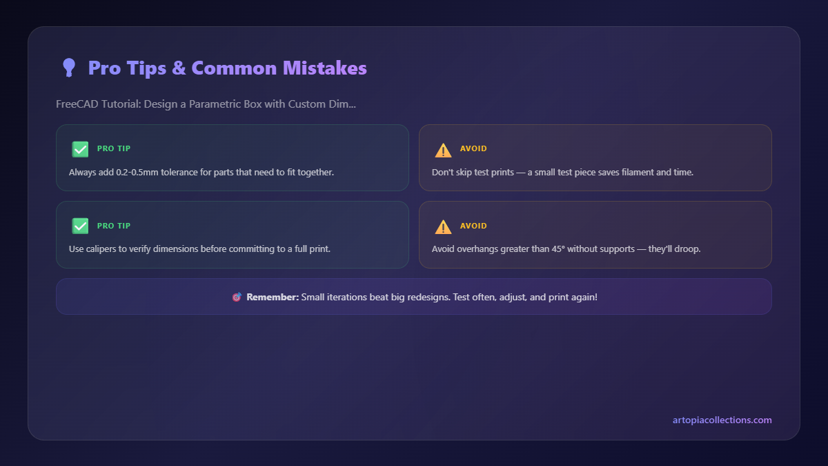
- Switch to Spreadsheet Workbench: From the Workbench dropdown, select "Spreadsheet".
- Create a New Spreadsheet: Click "Create spreadsheet".
- Define Parameters: In the spreadsheet, let's set up our variables. I usually put names in one column and values in the next.
- A1: Length, B1: 100mm
- A2: Width, B2: 80mm
- A3: Height, B3: 50mm
- A4: WallThickness, B4: 3mm
- Make Aliases: This is SUPER important. Right-click on cell B1, select "Properties...", go to the "Alias" tab, and type "Length" (or whatever you put in A1) in the alias field. Do this for all your dimension cells (B1-B4). This gives your values easily referenceable names.
Linking Dimensions to the Spreadsheet
Now, let's connect our model to these variables. This is the coolest part.
- Link Outer Sketch Dimensions:
- Go back to the Part Design Workbench.
- Double-click on "Sketch" (your first sketch) in the Model tree to edit it.
- Double-click on the "100mm" horizontal dimension. Instead of typing "100mm", click the small blue "fx" icon (Function Editor). Type
Spreadsheet.Lengthand press Enter. You should see it update. - Do the same for the "80mm" vertical dimension, linking it to
Spreadsheet.Width. - Close the Sketcher.
- Link Pad Height:
- Select "Pad" in the Model tree.
- In the Properties panel (usually at the bottom left), find the "Length" property under "Data". Click the small blue "fx" icon. Type
Spreadsheet.Heightand press Enter.
- Link Inner Sketch Wall Thickness:
- Double-click on "Sketch001" (your second sketch) in the Model tree.
- Double-click on one of the "3mm" wall thickness constraints. Click "fx" and type
Spreadsheet.WallThickness. Do this for all four wall thickness constraints. - Close the Sketcher.
- Link Pocket Depth:
- Select "Pocket" in the Model tree.
- In the Properties panel, find the "Length" property under "Data". Click "fx". Here’s where it gets mathematical: The pocket depth needs to be the total height minus the bottom wall thickness. So, type
Spreadsheet.Height - Spreadsheet.WallThickness. Press Enter.
And that, my friends, is it! Your box is now fully parametric. Go back to your Spreadsheet, change the values for Length, Width, Height, or WallThickness, and watch your 3D model magically update in real-time. It's truly a game-changer! You can even add more parameters for features like fillets, chamfers, or even custom cutouts later.
Why This Is Awesome for My Business (and Yours!)
Honestly, this workflow has transformed how I run ArtPopia Collections. When a client comes to me asking for a custom enclosure for their Raspberry Pi, or a unique organizer tray for their desk, I don't have to start from zero every time. I just open my parametric box file, punch in the new dimensions into the spreadsheet, maybe adjust the wall thickness if they want something super sturdy (or lighter), and bam! Ready to print. This saves me hours, literally hours, of design work per custom order.
And time, as we all know, is money. This efficiency means I can take on more custom orders, offer quicker turnarounds, and ultimately, grow my business. I can tell a customer, "Yes, I can make that exact storage box for your spices, and if you want it 20% smaller or 10% taller for your next batch, it'll be ready for print in minutes." That kind of flexibility is what sets a small business apart, especially in a competitive market like 3D printing here in India.
For printing these boxes, I usually stick with good old PLA. It's reliable, easy to print, and comes in a fantastic range of colours. For custom organizers, durability isn't usually the top concern, so PLA is perfect. I've had great results with eSun PLA+ and even some local Indian brands that have surprisingly good quality for about ₹1500-₹1800 per kg. Sometimes, if a client needs something stronger or heat-resistant, I might suggest PETG – it costs a bit more, say ₹2000-₹2500 per kg, but it’s worth it for functional parts. My Creality Ender 3 V2 NEO handles both like a champ, churning out clean prints with minimal fuss. Setting up the slicer (I use Cura) is pretty standard: 0.2mm layer height, 15-20% infill for sturdy boxes, maybe 0.4mm nozzle. The usual stuff, you know.
So, there you have it. A powerful tool, a fundamental project, and a workflow that can seriously boost your productivity. If you're serious about 3D printing, especially for custom work, learning FreeCAD and parametric design is, in my humble opinion, a non-negotiable skill. It might seem daunting at first, but stick with it. Watch some YouTube tutorials (there are some amazing Indian creators doing great FreeCAD content these days!), practice regularly, and don't be afraid to experiment. You'll be designing complex, adaptable models in no time.
Look, I'm passionate about making 3D printing accessible and profitable for everyone. This is just one of the many tricks I've picked up along the way. If you found this helpful, let me know! And hey, if you need some cool custom prints or just want to see what else we're making, swing by our collection page at ArtPopia Collections. We've got everything from intricate decor to functional everyday items, all designed with a whole lot of love and, you guessed it, often a sprinkle of parametric magic!


