Fusion 360 Thread Tool: How to Design Screw Threads for 3D Printing
This post guides you through using the Fusion 360 Thread Tool to design accurate screw threads. Learn how to optimize your designs for successful 3D printing of functional parts.

Ever been there? You’ve got this brilliant idea for a 3D printed enclosure, or maybe a fancy bottle opener with a removable cap, or even just a simple jig that needs to bolt together. You spend hours designing, printing, and then… the threads don't fit. They’re either too tight, too loose, or just plain strip out like a weak argument in a WhatsApp group chat. Ugh, the frustration is real, bhai! I've lost count of the number of times I've heard that sad tale, or lived it myself in the early days of Artopia Collections.
But fear not, my fellow maker! Today, we're diving deep into one of my absolute favourite, most used features in Fusion 360 – the Thread Tool. This isn't just about making something look pretty; it's about making functional, robust, and reliable screw threads for your 3D prints. And believe me, once you master this, a whole new world of design possibilities opens up for your projects, whether they’re personal passion projects or part of your small business here in India. Let's make some threads that actually work!
Why Functional Threads are a Game-Changer for 3D Printing
Look, anyone can download a pre-made STL of a nut and bolt. But what if you need a specific size? A custom pitch? A left-hand thread for some eccentric mechanism you're cooking up? That's where knowing how to design your own comes in. For my business, Artopia Collections, creating functional, robust prototypes and sometimes even final parts that assemble seamlessly is non-negotiable. We're talking about everything from custom enclosures for electronics to parts for our unique collections that need to screw together perfectly.
And honestly, there's a certain satisfaction, a pure joy, when two 3D printed parts, fresh off your Creality Ender 3 or Anycubic Kobra, screw together with that perfect, buttery smooth action. It's a testament to good design and careful printing. It elevates your print from a 'cool thing' to a 'useful, well-engineered thing'.
The Realities of 3D Printing Threads: It's Not Always Smooth Sailing
Before we jump into Fusion 360, let's just get real for a second about 3D printing threads. It's not like machining metal. Filament is softer, layer lines introduce imperfections, and your printer's calibration plays a huge role. Heat, cooling, nozzle diameter – all of these can subtly (or not so subtly) mess with your thread tolerances. So, while Fusion 360 will give you mathematically perfect threads, we need to account for the physical realities of FDM printing.
This is where the magic of understanding the tool and a bit of trial-and-error comes in. Don't get discouraged if your first attempt isn't perfect. Mine certainly weren't! I remember spending a whole evening trying to get a cap to screw onto a jar, only to realize I was making a fundamental mistake in Fusion. But hey, that's how we learn, right?
Fusion 360: Your Best Friend for Designing Threads
I personally think Fusion 360 is an absolute beast of a CAD software, especially for us small business owners and hobbyists in India. The personal use license is free (which is a huge deal when you're starting out and every rupee counts!), and it's incredibly powerful. It’s what I use for practically all my designs, from simple brackets to complex mechanisms. And the Thread Tool? Chef's kiss!
Let's dive into the specifics.
Locating and Understanding the Thread Tool
First things first, fire up Fusion 360. In your 'Design' workspace, you'll find the Thread tool under the 'Create' menu. Click on it, and a dialogue box will pop up. This is where all the magic happens.
Here are the key parameters you'll be playing with:
-
Face: This is the first thing you select. It’s the cylindrical face (either an extruded cylinder for an external thread, or a hole for an internal thread) where you want the threads to appear.
-
Modelled: THIS IS CRITICAL. For 3D printing, you almost always want to check this box. If you don't, Fusion 360 will only create a cosmetic thread – basically, just a texture map on the surface, which looks nice on screen but won't exist in your physical print. We need actual geometry! So, check 'Modelled'.
-
Type: This specifies the thread standard. For us in India, and generally for most mechanical applications, 'ISO Metric Profile' is your go-to. It’s universal and standard.
-
Size: This refers to the nominal diameter of your thread (e.g., M8, M10). Fusion will automatically suggest sizes based on the diameter of the cylindrical face you selected. So, if you made a 10mm diameter cylinder, it'll show M10 options.
-
Designation: This is where you pick the specific combination of size and pitch (e.g., M10x1.5, M10x1.0). The second number is the pitch – the distance between adjacent threads. A smaller pitch means finer threads, a larger pitch means coarser threads. For general 3D printing, especially in softer materials like PLA, coarser threads (larger pitch) tend to print better and be more robust against stripping.
-
Class: This defines the tolerance of the thread. For internal threads (nuts), you might see 6H. For external threads (bolts), 6g. These are standard fits. You generally don't need to mess with this unless you're doing highly specialized engineering, but it's good to know what it means.
-
Direction: Right Hand (standard, 'tighten clockwise') or Left Hand (for special applications where you need threads to loosen in the opposite direction). Most of the time, you'll use Right Hand.
-
Full Length: If checked, the thread will span the entire length of the selected cylindrical face. If unchecked, you can specify an 'Offset' (distance from the start) and 'Depth' (how long the thread should be).
Designing an External Thread (The Bolt)
Let's walk through an example. Say you want to make an M10 bolt with a 1.5mm pitch.
-
Create a Cylinder: Start by sketching a circle, extrude it to create a cylinder. For an M10 thread, I’d typically make the cylinder's diameter 10mm.
-
Activate Thread Tool: Go to 'Create' > 'Thread'.
-
Select Face: Click on the cylindrical face you just created.
-
Configure Settings:
- Check 'Modelled'.
- Type: ISO Metric Profile.
- Size: M10.
- Designation: M10x1.5 (this is a common, robust pitch).
- Direction: Right Hand.
- Full Length: Checked (or adjust offset/depth as needed).
-
Hit OK: Voila! You've got your external thread. Easy peasy lemon squeezy!
Printing Tip for External Threads: For best results, I usually print bolts vertically. This ensures the layer lines run along the thread, making them stronger and less prone to shearing off. You will need supports under the threads, but they are usually pretty easy to remove. If you print horizontally, you'll get faster prints but the threads will be significantly weaker along the layer lines.
Designing an Internal Thread (The Nut/Hole)
Now, this is where things get a *little* more nuanced for 3D printing. An internal thread needs to mate with an external one. If you just model an M10x1.5 internal thread in Fusion 360, and print it as is, it might be too tight for your M10x1.5 bolt.
Why? Because 3D printers, especially FDM ones, have tolerances. The filament expands a tiny bit, there's always a slight 'blobbiness' from the nozzle, and material shrinkage. This means an M10 hole might come out as 9.8mm or 9.9mm, or the internal peaks of the thread might be too close. We need to build in some wiggle room.
Here’s my preferred method for internal threads:
-
Create a Hole: Sketch a circle and extrude cut it to create your hole. For an M10 internal thread, the nominal diameter of the hole should be *slightly larger* than 10mm. I typically start with 10.1mm or 10.2mm for the initial hole diameter. Why? Because the thread cutting process will effectively reduce the effective diameter, and this slight oversize gives us a head start.
-
Activate Thread Tool: Go to 'Create' > 'Thread'.
-
Select Face: Click on the internal cylindrical face of your hole.
-
Configure Settings (with a crucial tweak!):
- Check 'Modelled'.
- Type: ISO Metric Profile.
- Size: M10.
- Designation: M10x1.5.
- Direction: Right Hand.
- Full Length: Checked (or adjust).
-
The Oversizing Trick: Now, before you hit OK, pay attention! To account for 3D printer tolerances, you generally want to slightly *oversize* your internal threads or *undersize* your external threads. For internal threads, my go-to is to use the 'Offset Face' tool. * After creating the thread, go to 'Modify' > 'Offset Face'. * Select all the faces of the internal thread. * Enter a positive offset value, typically between 0.05mm and 0.15mm. I usually start with +0.1mm. This literally expands the internal thread outwards, giving you that crucial extra clearance. It's a bit of an iterative process, so you might need to test print and adjust.
Printing Tip for Internal Threads: These are often best printed vertically too, though if they are shallow, horizontal can sometimes work. Supports will be needed for the overhangs of the threads inside the hole, which can be a pain to remove. Sometimes, printing with a smaller nozzle (0.2mm or 0.3mm) can yield cleaner internal threads, but it slows down printing dramatically. In my experience, a 0.4mm nozzle with good calibration is perfectly adequate.
Advanced Tip: Using the 'Scale' Command for Tolerance Adjustment
Another way to handle thread tolerance, especially if you're finding the offset face method a bit fiddly, is to scale the entire thread. This is particularly useful for external threads (bolts) where you might want to slightly undersize them without messing with the thread definition.
-
Design your external thread as usual (M10x1.5).
-
Once the thread is modelled, go to 'Modify' > 'Scale'.
-
Select the entire body of the bolt (or just the threaded section if it's a separate component).
-
Set the 'Scale Factor' to something like 0.99 or 0.98. This will uniformly shrink your bolt. For an M10 bolt, a scale factor of 0.99 would make it effectively an M9.9. This tiny reduction can be just enough to make it fit a standard M10 nut (either a printed one with a slight offset, or a metal one).
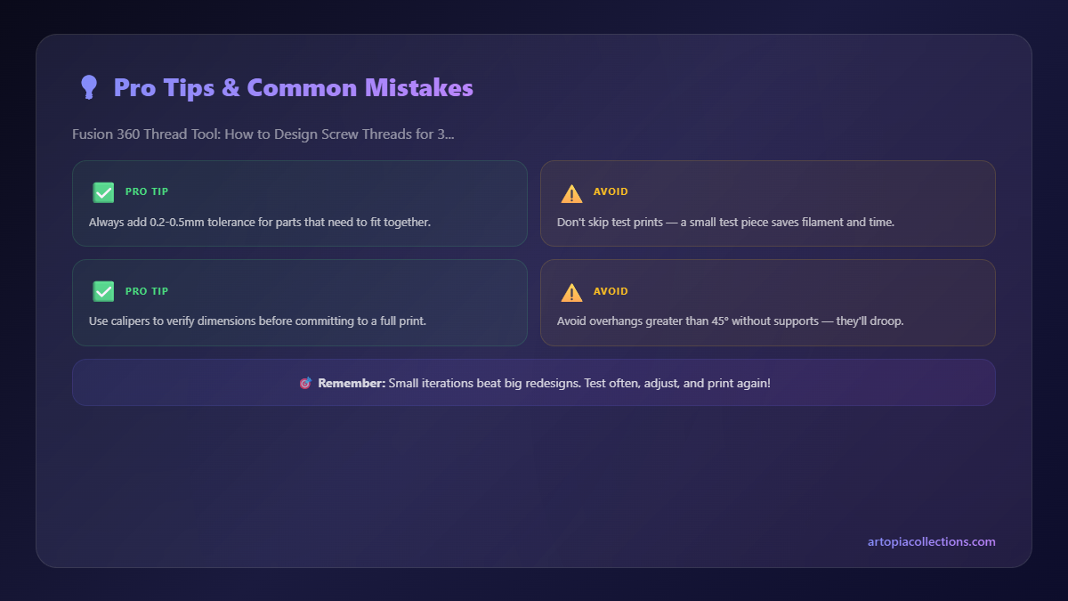
I find this method particularly useful when I'm designing a 3D printed bolt to fit a standard metal nut. Metal nuts are precise, so your printed bolt needs to be just a hair smaller to account for the slight dimensional inaccuracy of FDM. Again, trial and error is your best friend here. Print a small test piece (a few threads) and adjust until it fits perfectly.
Essential Tips for Successful 3D Printed Threads
Beyond the Fusion 360 settings, a few printing considerations can make or break your threaded parts.
-
Material Choice: For most functional threads, I stick with good quality PLA filament. Brands like eSun, Overture, and Oros 3D (an Indian brand!) are great and readily available here for about ₹800-₹1200 per kg. PLA is easy to print, fairly rigid, and strong enough for most light-duty applications. For stronger, more temperature-resistant threads, PETG is fantastic, though it can be a bit trickier to print cleanly. ABS? Only if you absolutely need the heat resistance and can handle the warping.
-
Print Settings:
- Layer Height: Go for finer layer heights (0.12mm to 0.16mm) for smoother threads. This reduces the staircase effect and helps with accuracy.
- Infill: 20-30% infill is usually fine for most threads, but for high-stress applications, go higher (e.g., 50% or even 100% for solid parts).
- Print Speed: Slow down! Seriously, print threads slower than you would a generic box. 30-40mm/s can make a huge difference in detail and quality.
- Cooling: Good cooling is essential to prevent warping and allow the filament to solidify properly, especially for overhangs in internal threads.
-
First Layer Adhesion: A perfect first layer is paramount. If your first layer is squished too much or not enough, it will propagate errors up the entire thread, leading to poor fit.
-
Post-Processing: Sometimes, even with perfect settings, you might have a tiny bit of stringing or a stray blob. A small pick tool or a hobby knife can help clean up the threads. For truly perfect internal threads, you can even buy an M10 tap (a tap and die set costs around ₹500-₹1500 on Amazon, depending on quality – check some out here) and manually clean out the printed threads. This is a bit advanced but gives you super clean, consistent results.
My Personal Workflow & Artopia Collections
For my business, the process generally starts with the desired function. Do I need to attach a camera mount to a tripod? That means a 1/4"-20 UNC thread. Do I need to create a custom clamp for a light stand? I'll probably design a robust M8 or M10 metric thread. I always design the male (external) thread first, then the female (internal) thread, applying the slight oversize or scaling to the male part. I then print a small test piece of both, maybe just 10mm long, and check the fit.
It’s iterative. Sometimes, I’ll print a test and find the threads bind after a couple of turns. Then I go back to Fusion, increase the offset on the internal thread by another 0.05mm, or reduce the scale on the external one. It’s a dance, but once you find that sweet spot for your specific printer and filament combination, you can usually stick to those offsets for similar threads.
For instance, for some of our electronic enclosures at Artopia Collections, we use 3D printed covers that screw directly onto the main body. Getting these threads right ensures a snug, secure fit without the need for additional hardware, which saves us money and simplifies assembly. It’s little details like this that make a difference in product quality and customer satisfaction.
Go Forth and Thread!
So there you have it, my friends. Designing functional screw threads in Fusion 360 for 3D printing is not some dark art reserved for engineers. It's a skill that's totally within your grasp, and it will dramatically expand what you can create with your 3D printer. Remember the key takeaways: 'Modelled' is your friend, ISO Metric Profile is your standard, and a little bit of tolerance adjustment (offsetting faces or scaling) is your secret weapon.
Don't be afraid to experiment. Print some test pieces. Learn from what doesn't work. Before you know it, you'll be threading like a pro, and your 3D printed creations will be more functional, more robust, and just plain cooler than ever before. Happy printing, and may your threads always be smooth!


